- Blogs
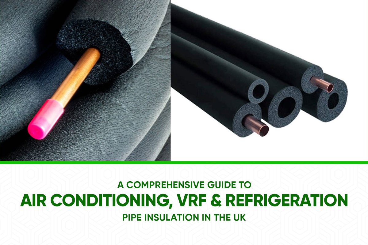
- A Comprehensive Guide to Air Conditioning, VRF & Refrigeration Pipe Insulation in the UK
A Comprehensive Guide to Air Conditioning, VRF & Refrigeration Pipe Insulation in the UK


1. Introduction: The Critical Role of Pipe Insulation (Pipe Lagging) in HVACR Systems
The insulation applied to pipework (often referred to as pipe lagging or simply lag) within Heating, Ventilation, Air Conditioning (AC), and Refrigeration (HVACR) systems is an essential component that, despite often being concealed from view, fundamentally dictates the system's overall performance, energy consumption, and operational lifespan. Its role extends far beyond merely covering pipes; it is an active contributor to the efficiency and safety of the entire installation.
The core benefits of correctly specified and installed pipe lagging are multifaceted. Firstly, energy conservation is a primary advantage. Insulation minimises undesirable heat gain in the case of cold pipework, such as chilled water or refrigerant lines for an air conditioner or AC unit, and reduces heat loss from hot gas lines, particularly relevant in Variable Refrigerant Flow (VRF) systems. This thermal control directly lessens the operational burden on key equipment like chillers and compressors, leading to reduced energy expenditure and lower utility bills.
Secondly, condensation control is a critical function, especially for pipework operating at temperatures below the ambient dew point. Effective pipe insulation prevents the formation of condensation on cold pipe surfaces. If left uncontrolled, condensation can lead to a cascade of problems including water damage to surrounding building fabric, corrosion under insulation (CUI) which degrades the pipework itself, and the proliferation of mould, which can negatively impact indoor air quality and occupant health, especially with modern aircon systems.
Thirdly, insulation contributes to overall system efficiency and longevity. By helping to maintain the correct operating temperatures for the fluids within the pipes, the pipe lag ensures that the system performs as designed. It also protects the pipework from the detrimental effects of corrosion and excessive temperature fluctuations, thereby extending its service life.
Finally, safety and compliance are important considerations. Insulation can protect personnel from accidental burns or cold-related injuries by maintaining safe surface temperatures on pipework. Furthermore, specific insulation materials are chosen for their fire performance characteristics to meet stringent UK Building Regulations, contributing to the overall fire safety strategy of a building.
This guide is specifically tailored to the UK context, focusing on materials commonly available and practices compliant with relevant British Standards and Building Regulations. The efficiency of an HVACR system, including any air conditioner, is not determined in isolation by its primary components such as chillers or condensing units. Instead, it is significantly influenced by elements like pipework insulation. HVACR systems function by transporting energy, in the form of heated or cooled fluids, through extensive pipe networks. If these pipes are uninsulated or inadequately lagged, they become significant points of uncontrolled heat exchange with the surrounding environment. Consequently, chillers must operate more intensively to sustain low temperatures in cooling systems, or valuable heat is dissipated before reaching its intended point of use in heating applications. This results in a direct escalation of energy consumption, potentially offsetting some of the efficiency benefits gained from using high-specification primary equipment. Such inefficiencies lead to increased operational costs and a larger environmental carbon footprint. Within the broader UK objective of achieving net-zero emissions and enhancing building energy performance, as underscored by recent updates to regulations like Part L, optimising every facet of the system, including its pipe lagging, is indispensable. This reflects a comprehensive strategy towards achieving greater energy efficiency.
2. Understanding Common Pipe Insulation Materials for AC and Aircon Systems in the UK
The selection of an appropriate pipe lagging material is fundamental to the performance of any HVACR pipework system, including AC and aircon installations. Different materials possess distinct properties making them suitable for specific applications and environmental conditions. The UK market offers a range of insulation types, each with its own thermal characteristics, fire performance, moisture resistance, and installation requirements.
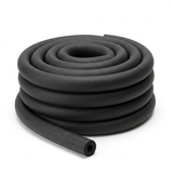
2.1 Flexible Elastomeric Foams (FEF)
Flexible elastomeric foams are extensively used in HVACR applications due to their inherent flexibility, which simplifies installation around complex pipe configurations, and their excellent resistance to water vapour. This latter characteristic is particularly important for preventing condensation on cold lines.
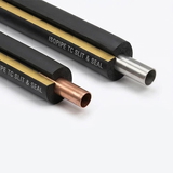
2.1.1 Nitrile Rubber (e.g., Armaflex Class O, Kaimann Kaiflex ST) 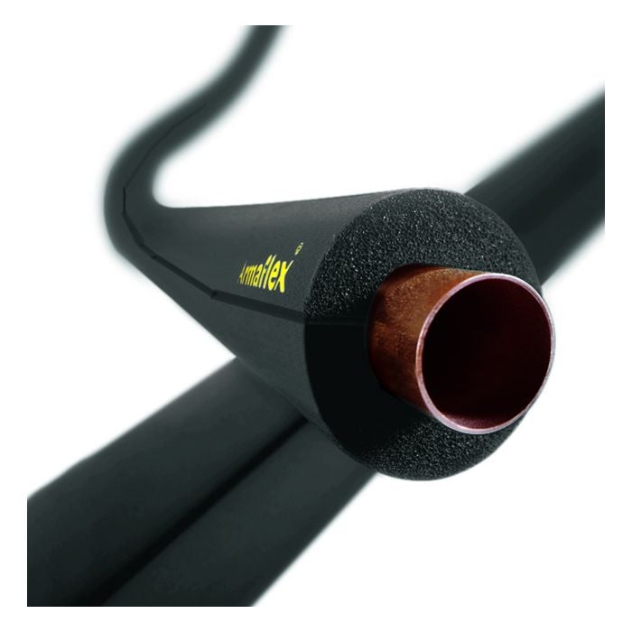
-
Properties: Nitrile rubber insulation features a closed-cell structure that provides an integral vapour barrier, indicated by a high water vapour diffusion resistance factor (mu-value), typically 7,000 or greater, or 10,000 or greater. This significantly reduces the risk of moisture ingress and subsequent corrosion under insulation. Its inherent flexibility allows for ease of installation, particularly around bends, valves, and fittings. The material exhibits low thermal conductivity, commonly around 0.033 W/mK at 0 degrees C, contributing to effective thermal control. Nitrile rubber insulation is suitable for a broad operating temperature range, often cited as -50 degrees C to +105 degrees C or +110 degrees C. In terms of fire performance, leading nitrile rubber products typically achieve a Euroclass B/BL-s2,d0 or B-s3,d0. Some formulations also incorporate antimicrobial protection to inhibit mould and bacterial growth.
-
Applications: It is a prevalent choice for insulating refrigeration pipework, chilled water lines, and general air conditioner (AC) systems to prevent condensation formation and minimise energy losses. It is also suitable for hot water services, provided the operating temperatures remain within the material's specified limits.
-
Considerations: If used externally, standard nitrile rubber insulation requires protection from UV radiation, as prolonged exposure can cause degradation unless the product is specifically formulated for UV resistance or is coated with a protective finish. The correct application and sealing of adhesives at all seams and joints are critical to maintain the integrity of the vapour barrier.
2.1.2 EPDM Rubber (Ethylene Propylene Diene Monomer)
-
Properties: EPDM rubber insulation also possesses a closed-cell structure. Its standout characteristic is excellent resistance to UV radiation, ozone, and general weathering, making it highly durable for outdoor applications without the need for additional protective coatings. EPDM typically offers a higher maximum operating temperature capability compared to standard nitrile rubber, with some products rated up to +150 degrees C (system ratings with adhesives may be lower, e.g., 125 degrees C). It maintains good flexibility at low temperatures (down to -50 degrees C) and offers good resistance to water vapour transmission due to its non-polar nature, which also contributes to resistance against many acids and alkalis.
-
Applications: EPDM is particularly well-suited for insulating external pipework, solar thermal systems, and high-temperature lines. This includes the hot gas (high-pressure vapour) lines found in some VRF/VRV air conditioning (aircon) systems, where operating temperatures can exceed the limits of standard nitrile rubber.
-
Considerations: EPDM insulation can be more costly than nitrile rubber. For VRF systems, manufacturer specifications often explicitly require EPDM or an equivalent high-temperature resistant material due to the elevated operating temperatures of certain lines. Compared to standard NBR/PVC (Nitrile Butadiene Rubber/Polyvinyl Chloride) foams, EPDM generally offers superior outdoor durability and a wider operational temperature window, especially at the higher end. While NBR/PVC provides good insulation, its UV resistance is typically lower, often necessitating protective coatings for external use, and its maximum service temperature is generally lower than EPDM's. EPDM's non-polar characteristic also tends to give it an edge in water resistance over the more polar NBR/PVC in very humid conditions or with prolonged chemical exposure.
-
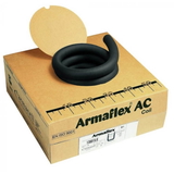
UK Brands Utilising EPDM: A prominent brand offering EPDM or EPDM-like high-temperature and UV-resistant flexible elastomeric foam in the UK is Armacell, particularly with their HT/Armaflex range. This product line is often specified for applications such as solar pipework and other external or high-temperature HVACR duties where the enhanced properties of EPDM are beneficial. While other manufacturers supply various elastomeric foams, the HT/Armaflex range is frequently cited when EPDM characteristics are required.
2.2 Rigid Foam Insulation
Rigid foam insulation materials are characterised by their very low thermal conductivities, offering high thermal resistance, and their good structural properties.
2.2.1 Phenolic Foam (e.g., Kingspan Kooltherm Pipe Insulation)
-
Properties: Phenolic foam is renowned for its exceptionally low thermal conductivity, with values typically ranging from 0.018 W/mK to 0.025 W/mK. This high thermal efficiency means that specified insulation performance can often be achieved with a thinner layer of material compared to other insulants. It has a predominantly closed-cell structure (over 90 percent), which inherently offers good moisture resistance. However, for cold and chilled water applications, a factory-applied foil vapour barrier jacket is standard and essential to ensure long-term performance. Phenolic foam exhibits good fire performance, with foil-faced products commonly achieving a Euroclass BL-s1,d0 rating. It also possesses good compressive strength, making it suitable for applications where some load-bearing capability is required. The typical operating temperature range is from -50 degrees C to +110 degrees C.
-
Applications: Phenolic foam is suitable for a broad spectrum of HVACR pipework, including Low-Temperature Hot Water (LTHW) systems, chilled water lines, refrigeration pipework, and general air conditioning applications where high thermal performance is a key requirement for the pipe lag.
-
Considerations: For all applications on pipework operating below ambient temperature, the integrity of the vapour barrier is paramount. All joints and penetrations must be meticulously sealed with a matching foil tape to prevent moisture ingress. Being a rigid material, fabricating sections for complex shapes or fittings may require more precise cutting compared to flexible elastomeric foams.
2.3 Mineral Wool (Rock Wool / Stone Wool)
-
Properties: Mineral wool is a non-combustible insulation material, typically achieving a Euroclass A1 or A2-s1,d0 fire rating, which signifies excellent fire resistance. It provides good thermal performance, although its thermal conductivity (e.g., 0.033 W/mK to 0.040 W/mK) is generally higher than that of phenolic foam or some elastomeric foams. Mineral wool also offers excellent acoustic insulation properties, helping to reduce noise transmission from pipework. It can withstand very high service temperatures, often up to 250 degrees C or even 700 degrees C and beyond, depending on the specific product formulation. While the fibres themselves are water repellent, mineral wool insulation is highly permeable to water vapour, having a water vapour diffusion resistance factor (mu-value) close to 1.
-
Applications: Mineral wool is frequently specified for the thermal and acoustic insulation of heating pipes, LTHW systems, and in situations where a high degree of fire resistance is mandated by regulations or project specifications. It can be used on cold or chilled water lines, but this application absolutely requires the correct installation of a separate, continuous, and meticulously sealed vapour barrier to prevent moisture ingress.
-
Considerations: The critical factor for mineral wool on cold lines is the vapour barrier. Often, mineral wool pipe sections are supplied with a factory-applied foil facing, but all joints, seams, and penetrations must be thoroughly sealed with appropriate tapes to ensure the vapour barrier's continuity. Failure to achieve a perfect seal will lead to condensation forming within the insulation, severely degrading its thermal performance and potentially causing CUI. Achieving a durable and effective vapour seal with fibrous materials can be more labour-intensive compared to using closed-cell insulation materials.
2.4 Fibreglass (Glass Mineral Wool)
-
Properties: Fibreglass insulation shares many characteristics with mineral wool (rock wool). It offers good thermal insulation performance and is non-combustible, often achieving a Euroclass A1 or A2 fire rating. It is commonly available in pre-formed pipe sections, frequently with a factory-applied aluminium foil facing that can serve as a vapour barrier if all joints are properly sealed.
-
Applications: Fibreglass is used for insulating hot and cold water pipes, HVAC ductwork, and for general thermal insulation purposes in building services.
-
Considerations: Similar to mineral wool, when fibreglass insulation is used for cold or chilled applications, the integrity and continuity of the vapour barrier (whether factory-applied or site-applied) are of utmost importance to prevent condensation and maintain thermal performance. Handling fibreglass can cause skin irritation for some individuals, so the use of appropriate personal protective equipment (PPE) is recommended.
2.5 Polyethylene Foam
-
Properties: Polyethylene foam is a closed-cell, flexible insulation material that is relatively low in cost. It provides reasonable thermal insulation and has some inherent water vapour resistance.
-
Applications: It is commonly used for insulating domestic heating and plumbing pipes and some less demanding air conditioning applications.
-
Considerations: Polyethylene foam generally has lower maximum service temperature limits and potentially lower fire performance ratings compared to materials like nitrile rubber or phenolic foam. It may not be suitable for more demanding commercial refrigeration or VRF system applications. If used for buried pipework, it must be protected from crushing by soil pressure, for example, by being installed within protective ducting.
The water vapour diffusion resistance factor, or "mu-value," is a crucial property for insulation materials intended for use on cold pipework. A high mu-value, characteristic of closed-cell foam insulations such as nitrile rubber, EPDM, and phenolic foam, is fundamental for long-term performance.
This is because cold pipes typically operate at temperatures below the dew point of the surrounding air, creating a vapour pressure gradient that drives moisture from the ambient air towards the cold pipe surface. If the insulation material is permeable to water vapour (i.e., has a low mu-value, as is the case with mineral wool without an effective vapour barrier), water vapour will migrate through the insulation and condense on the cold pipe surface.
This internal or sub-surface condensation has multiple detrimental effects: it drastically reduces the thermal performance of the insulation (as water is a poor insulator compared to air), it can lead to corrosion under insulation (CUI), which can damage or destroy the pipework, and it can promote mould growth. Consequently, materials with a high inherent mu-value, or systems where a vapour barrier can be impeccably applied and maintained, are essential for the durability and efficiency of refrigeration and chilled water systems. This directly aligns with the emphasis placed on condensation control in standards such as BS 5422.
The choice of insulation material also has a cascading effect on installation complexity, the need for ancillary materials (such as separate vapour barriers, specialised adhesives, or protective coatings), and long-term maintenance requirements. Different materials vary in their physical form (e.g., flexible versus rigid) and inherent properties (e.g., closed-cell versus open-cell or fibrous structure). For instance, a flexible closed-cell material like nitrile rubber may be quicker to install and require fewer additional sealing materials to ensure its vapour barrier function compared to a fibrous material like mineral wool on a chilled water line.
The latter would necessitate a separate, meticulously sealed vapour barrier and potentially more intricate jointing techniques. Similarly, using EPDM for outdoor applications might obviate the need for the separate UV protective coatings that other materials would require if exposed to sunlight. These factors influence not only the initial material cost but also the total installed cost and the overall lifecycle cost of the insulation system. A material that appears cheaper on a per-metre basis might ultimately prove more expensive if it demands more labour for installation, additional barrier materials, or more frequent inspections and repairs due to susceptibility to moisture ingress or UV degradation.
Therefore, specifiers must adopt a holistic system approach, aligning their material choice with the specific demands of the application (such as operating temperature, environmental conditions, and fire risk) and the practicalities of achieving a durable and effective installation, as guided by standards like BS 5970.
Table 1: Comparative Overview of Common HVACR Pipe Insulation Materials in the UK
| Material Type | Typical Thermal Conductivity (W/mK at 10 degrees C mean) | Common Euroclass Fire Rating (Faced) | Water Vapour Resistance | Typical Max. Service Temperature (degrees C) | Key Advantages for HVACR | Key Considerations for HVACR |
|---|---|---|---|---|---|---|
| Nitrile Rubber | 0.032 - 0.036 | BL-s2,d0 or B-s3,d0 | Very High (inherent vapour barrier, mu 7,000-10,000 or greater) | +105 to +110 | Flexible, good condensation control, easy to install, built-in vapour barrier, some with antimicrobial. | Requires UV protection outdoors unless specified. Seam integrity is vital. Lower max temp than EPDM. |
| EPDM Rubber | Similar to Nitrile | Often B or BL rated | High (inherent vapour barrier) | +125 to +150 | Excellent UV/weather resistance, higher temperature resistance, good for outdoor & VRF hot gas lines. | Can be more expensive. Check manufacturer specs for VRF. Better outdoor durability than standard Nitrile. |
| Phenolic Foam | 0.018 - 0.025 | BL-s1,d0 (foil-faced) | High (closed cell, foil facing acts as vapour barrier) | +110 | Very high thermal efficiency (thinner sections), good fire performance, good moisture resistance with foil. | Rigid, requires careful sealing of foil joints for vapour barrier integrity on cold lines. |
| Mineral Wool | 0.033 - 0.040 | A1 or A2-s1,d0 | Low (mu approx 1, requires separate vapour barrier for cold lines) | +250 to +700+ | Excellent fire resistance, good acoustic properties, high temperature suitability. | Must have a perfectly sealed vapour barrier for cold/chilled lines. Can be bulky. |
| Fibreglass | Similar to Mineral Wool | A1 or A2 (often) | Low (requires effective vapour barrier for cold lines) | Varies, typically up to 230-250 | Good thermal insulation, non-combustible. | Vapour barrier integrity is crucial for cold lines. Handling may cause irritation. |
| Polyethylene Foam | approx 0.034 - 0.040 | Often E or F | Moderate (closed cell) | approx +80 to +90 | Low cost, flexible, easy to install for domestic/light duties. | Lower temperature limits and fire performance than others. Not for demanding commercial/refrigeration. Requires protection if buried. |
3. Key UK Standards and Regulations Governing Pipe Lagging and Air Conditioner Insulation
Navigating the regulatory landscape is essential for ensuring that pipe insulation installations, including pipe lagging for an air conditioner, are not only effective but also compliant with UK law. Several British Standards and parts of the Building Regulations provide the framework for specifying, installing, and verifying pipe insulation in HVACR systems.
3.1 BS 5422:2023 – Method for specifying thermal insulating materials 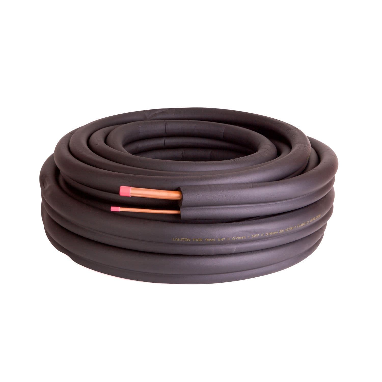
-
Purpose: BS 5422:2023 provides a methodology for determining the appropriate thickness of thermal insulation (pipe lag) for pipework, ductwork, and associated equipment. Its scope covers a wide temperature range, from -40 degrees C to +700 degrees C, making it applicable to most HVACR systems found in domestic, commercial, and industrial buildings. The standard aims to guide designers, specifiers, contractors, and manufacturers in achieving effective thermal control.
-
Key Requirements for HVACR: A primary focus of BS 5422 is the conservation of energy and the control of condensation. It contains tables and calculation methods to determine minimum insulation thicknesses. These calculations take into account factors such as pipe size, the temperature of the fluid within the pipe, ambient environmental conditions (temperature and relative humidity), and the thermal conductivity of the chosen insulation material. For instance, specific tables such as Table 7 are provided for condensation control on chilled water lines, and Table 2 for refrigeration pipework under various ambient conditions. The standard also considers the impact of surface emissivity of the insulation finish and different environmental scenarios on the required insulation thickness.
-
2023 Updates: The 2023 revision of BS 5422 introduced several important changes. Notably, it replaced the older UK 'National Class' fire ratings with the current Euroclass system, aligning with broader European harmonisation. It also introduced optional 'enhanced performance' tables, which specify greater insulation thicknesses to achieve higher levels of energy saving. Other changes include updates to pipe diameter referencing and the explicit treatment of single-wall plastic pipes as having no inherent insulative value for calculation purposes.
-
Relevance: BS 5422 is an indispensable tool for specifiers. Adherence helps ensure that installations meet minimum required levels of thermal performance and effectively prevent surface condensation. It also assists in balancing economic considerations with environmental objectives, such as reducing carbon dioxide emissions through improved energy efficiency.
3.2 BS 5970:2012 – Code of practice for thermal insulation of pipework, ductwork, associated equipment and other industrial installations
-
Purpose: While BS 5422 deals with what thickness of insulation is required, BS 5970:2012 provides comprehensive recommendations on how to design, select materials for, apply, and maintain thermal insulation systems. It covers an operational temperature range of -100 degrees C to +870 degrees C.
-
Key Areas Covered:
- Design Considerations: This includes factors that affect the planning and programming of insulation work and the necessary exchange of design data between parties.
- Materials Selection: The standard offers guidance on selecting appropriate insulating materials, as well as materials for securing the insulation, vapour barriers, and protective finishes or cladding.
- Application Methods: Detailed recommendations are provided for surface preparation prior to insulation, methods of securing insulation, and specific techniques for applying insulation to cold systems (e.g., refrigeration) and hot systems. It also covers the application of indoor finishes and weather-resistant finishes for external installations.
- Corrosion Prevention: BS 5970 addresses the critical issue of corrosion under insulation (CUI), providing guidance on how to mitigate this risk.
- Weatherproofing and Cladding: The standard includes requirements for protecting insulation from environmental factors such as weather and from mechanical damage, often through the use of cladding.
-
Relevance: BS 5970 is the key standard for ensuring the quality of workmanship and the long-term durability and performance of an insulation system. It complements BS 5422 by focusing on the practical execution of the insulation work.
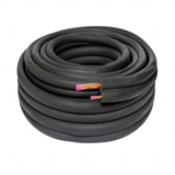
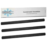
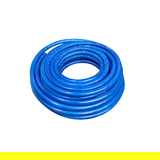
Buy Air Conditioning, VRF & Refrigeration Pipe Insulation

3.3 Building Regulations Part L (Conservation of Fuel and Power)
-
Purpose: Part L of the Building Regulations sets the legal standards for the energy performance of new and existing buildings in England (with broadly similar, though distinct, regulations in Wales, Scotland, and Northern Ireland). Its primary aim is to conserve fuel and power.
-
Requirements for Pipework: Part L mandates the insulation of various types of pipework, including those for aircon units, to limit heat losses and improve energy efficiency. This typically includes primary heating circuit pipes, domestic hot water pipes (including for at least one metre from hot water storage cylinders), and any heating or hot water pipes that pass through unheated spaces or voids. The overarching goal is to reduce carbon emissions from buildings.
-
Recent Updates (e.g., June 2022/2023): Recent updates to Part L have placed further emphasis on energy efficiency, for example, by promoting lower flow temperatures for heating systems (maximum 55 degrees C in many cases). A key stipulation is that all newly installed pipework associated with heating and hot water systems must now be insulated.
-
Relevance: Compliance with Part L is a legal requirement for most construction and renovation projects involving building services. Failure to comply can result in enforcement action by local building control bodies. These regulations directly influence the energy efficiency of buildings and their associated operational running costs.
3.4 Building Regulations Approved Document B (Fire Safety)
-
Purpose: Approved Document B provides practical guidance on how to meet the fire safety requirements stipulated in the Building Regulations for England. It is split into two volumes: Volume 1 for Dwellings, and Volume 2 for Buildings other than Dwellings.
-
Requirements for Insulation Materials:
- Reaction to Fire: Insulation materials must be classified according to their reaction to fire performance using the Euroclass system (e.g., Euroclass A1, B, C, etc., along with additional classifications for smoke production 's' and the generation of flaming droplets 'd'). The older UK national classification 'Class O' has been largely superseded by the Euroclass system in the Building Regulations. Approved Document B specifies the minimum Euroclass performance levels required for insulation materials depending on the type of building, its height, the location of the insulation, and the specific application. For instance, in buildings other than dwellings, the complete insulation assembly (whether faced or unfaced) is often required to achieve Class B-s3, d2 or better.
- Cavity Barriers & Fire Stopping: The document includes requirements for the installation of cavity barriers and fire stopping measures. These are designed to prevent the unseen spread of fire and smoke through concealed cavities within the building structure and at points where services (like pipework) penetrate fire-resisting elements. Insulation systems on pipework or ductwork that pass through fire-resisting divisions (such as walls or floors) must be detailed in such a way that they maintain the fire resistance rating of that division.
-
Relevance: The requirements of Approved Document B are critical for ensuring life safety and protecting property in the event of a fire. The choice of insulation materials can be significantly influenced, and in some cases restricted, by these fire safety regulations, particularly in high-rise buildings, buildings with vulnerable occupants, or in specific locations such as escape routes.
Achieving compliance in HVACR pipe insulation is not a matter of adhering to a single standard in isolation. Instead, it involves navigating an interconnected framework of regulations where energy efficiency (guided by Part L and BS 5422), the quality and durability of installation (guided by BS 5970), and fire safety (guided by Approved Document B) all exert significant influence. These requirements can sometimes create complex decision-making scenarios for specifiers and installers.
For example, BS 5422 dictates the necessary thickness of insulation to achieve a certain thermal performance, while Part L mandates that pipework be insulated to conserve energy. BS 5970 provides detailed guidance on how this insulation should be correctly installed to ensure its effectiveness and longevity. Concurrently, Approved Document B sets out stringent fire performance criteria for the insulation materials themselves. A material chosen for its superior thermal properties (to meet BS 5422 and Part L requirements) might not achieve the necessary Euroclass fire rating for a particular location as stipulated by Approved Document B. For instance, some highly efficient foam insulation products might have a lower fire classification compared to non-combustible mineral wool.
Similarly, achieving the continuous layer of insulation advocated by BS 5970 might be complicated by the need to incorporate fire-stopping measures at service penetrations through fire-rated walls or floors. This means that specifiers and installers must consider all relevant standards simultaneously. A decision optimised for one aspect, such as selecting the thinnest possible insulation to meet thermal performance targets, could inadvertently lead to non-compliance with another, such as fire safety requirements. This necessitates a holistic understanding of the regulatory landscape and careful selection and detailing of materials. The increasing stringency of these regulations, exemplified by the 2023 updates to BS 5422 and the ongoing evolution of Part L, suggests that this complexity is likely to increase, further underscoring the need for competent and knowledgeable professionals in the field.
The transition from UK national fire classifications, such as the widely recognised 'Class O', to the European Euroclass system (defined in BS EN 13501-1) represents a significant change that has required considerable adaptation within the UK construction industry. This shift impacts how insulation products are specified, tested, and understood. It is important to recognise that this is not a direct, like-for-like replacement, and a thorough understanding of the nuances of Euroclass ratings (e.g., B-s1,d0) is now vital for compliance and safety. UK Building Regulations now clearly reference Euroclasses as the prevailing standard.
The Euroclass system offers a more comprehensive assessment of a material's fire behaviour compared to the older national classes. While 'Class O' primarily addressed surface spread of flame and fire propagation, Euroclass ratings also evaluate heat release, smoke production (classified as s1, s2, or s3, with s1 being the least smoke), and the occurrence of flaming droplets or particles (classified as d0, d1, or d2, with d0 meaning no droplets). This multi-faceted approach provides a more detailed and realistic indication of how a material will behave in a fire. Consequently, specifiers can no longer simply request 'Class O' insulation.
They must now specify the required Euroclass rating appropriate for the application and building type (e.g., BL-s1,d0 for pipe insulation in certain defined areas). Manufacturers have had to re-test their products to these European standards and declare their performance accordingly, often printing the Euroclass rating on product packaging and the insulation itself. Installers, in turn, need to be familiar with these new classifications to ensure they are fitting compliant materials. Misunderstanding or misapplying these ratings can lead to installations that are not only non-compliant but also potentially unsafe. The 's' (smoke) and 'd' (droplets) classifications are particularly significant for life safety, as smoke inhalation is a primary cause of casualties in fires, and flaming droplets can contribute to rapid fire spread. This harmonisation with European standards, while aiming to simplify cross-border trade, necessitates an ongoing educational effort within the UK construction sector to ensure the new system is correctly interpreted and applied.
Table 2: Overview of Key UK Pipe Insulation Standards & Regulations
| Standard/Regulation | Primary Focus for Pipe Insulation | Key HVACR Relevance |
|---|---|---|
| BS 5422:2023 | Method for specifying thermal insulating materials; determining insulation thickness. | Determines minimum insulation thickness for energy conservation and condensation control based on pipe size, temperatures, and material properties. |
| BS 5970:2012 | Code of practice for the design, material selection, application, and maintenance of insulation. | Guides the quality of installation, ensuring durability, correct application of vapour barriers, weatherproofing, and corrosion prevention. |
| Building Regulations Part L | Conservation of fuel and power; setting energy performance standards for buildings. | Legally mandates insulation of heating and hot water pipework to limit energy loss and reduce carbon emissions. |
| Building Regulations Approved Document B | Fire safety requirements for buildings. | Sets legally required fire performance standards (Euroclasses) for insulation materials and systems, including cavity barriers and fire stopping. |
4. Best Practices for Installing HVACR Pipe Lagging, Including for AC Units
The selection of high-quality insulation materials is only half the battle; correct installation of pipe lagging is equally critical to achieving the desired thermal performance, condensation control, and system longevity. Poor installation practices can significantly compromise the effectiveness of even the most advanced insulation products, leading to energy wastage, moisture problems, and premature system failure. Adherence to best practices, as outlined in standards like BS 5970 and manufacturer guidelines, is therefore paramount.
4.1 Preparation and Material Selection Verification 
Before any insulation work commences, a thorough assessment of the site and verification of materials are essential steps. Installers should evaluate the pipework system, noting the operating temperatures and pressures of the fluids being carried, and assess the surrounding environment, including ambient temperature, humidity levels, and potential for mechanical damage or UV exposure. It is crucial to confirm that the chosen insulation material and its specified thickness are appropriate for the specific application, aligning with the requirements of BS 5422 and the insulation manufacturer’s recommendations for the anticipated service temperatures and conditions.
For VRF systems, particular attention must be paid to the VRF equipment manufacturer's specific insulation requirements, especially concerning temperature ratings for different lines within the air conditioner system. Pipe surfaces must be clean, dry, and free from any contaminants such as oil, dust, or rust before insulation is applied. Adhesives and insulation materials will not bond effectively to soiled or unprepared surfaces. It is also a standard safety precaution that HVACR systems should not be in operation (i.e., not carrying heated or chilled fluids) during the insulation installation process.
4.2 Ensuring Complete and Continuous Coverage
For insulation to perform effectively, it must provide complete and continuous coverage over all surfaces of the pipework system. This includes not only straight runs of pipe but also all bends, elbows, tees, valves, flanges, and other fittings. Even small uninsulated sections can act as significant thermal bridges, creating localised points for heat loss or gain, and becoming prime locations for condensation to form on cold lines.
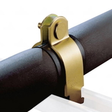
Pipe supports are common points where thermal bridging can occur. To prevent this, insulation should be continuous through pipe support locations. This is typically achieved by using load-bearing insulating inserts made from high-density materials like phenolic foam or mineral wool, or by employing proprietary insulated pipe supports. The historical practice of using wooden blocks as pipe supports is now considered contrary to the guidance in BS 5422:2023, as wood is not an effective insulating material and compresses the primary insulation. Insulation sections should be correctly sized to fit snugly around the pipe and must butt together tightly at all joints to minimise gaps.
4.3 Sealing Joints and Seams
The integrity of all joints and seams in the insulation system is critical, particularly for maintaining the effectiveness of vapour barriers on cold lines. For flexible elastomeric foams and some other types of foam insulation, manufacturer-recommended adhesives should be applied evenly to both surfaces of butt joints and longitudinal seams. The adhesive should be allowed to tack dry according to the manufacturer's instructions before the surfaces are pressed firmly and evenly together to achieve a strong bond.
Appropriate pressure-sensitive tapes, such as matching aluminium foil tape for foil-faced insulation products or specialised UV-resistant PVC tape for weatherproof outdoor insulation systems, should be used to seal all external joints and seams. Tapes should be applied smoothly and with sufficient overlap to ensure a durable seal. For pipework operating at low temperatures, a technique known as "wet sealing" is often recommended for butt joints in elastomeric insulation. This involves applying a thin film of adhesive to the compressed edges of the joint as it is pulled slightly apart, ensuring a robust and complete seal when the joint is released and pressed together.
4.4 Vapour Barriers – Essential for Cold Applications
A correctly installed and continuous vapour barrier is arguably the most critical component of an insulation system for pipework operating below the ambient dew point, such as chilled water and refrigeration lines. Its purpose is to prevent water vapour from the warmer, more humid ambient air from migrating through the insulation material to the cold surface of the pipe, where it would cool and condense. Uncontrolled condensation within or beneath the insulation can lead to a host of problems, including reduced thermal performance, corrosion under insulation (CUI), and mould growth.
Certain insulation materials, primarily closed-cell foams like nitrile rubber, EPDM, and phenolic foam (when supplied with an intact factory-applied foil facing), possess a high intrinsic resistance to water vapour diffusion (characterised by a high mu-value) and therefore act as their own vapour barrier, provided all joints and penetrations are properly sealed.
In contrast, fibrous or open-cell insulation materials, such as mineral wool and fibreglass, have very low mu-values (i.e., they are highly permeable to water vapour). When these materials are used on cold lines, they must be completely encapsulated by a separate, continuous, and impeccably sealed vapour barrier. This barrier is typically a foil sheet, a reinforced foil laminate, or a specialised vapour barrier coating. The vapour barrier must always be installed on the warm side (which is the outer surface) of the insulation on cold pipework. Extreme care must be taken to ensure its continuity; all joints, seams, penetrations (e.g., for supports or valves), and terminations must be meticulously sealed according to manufacturer instructions and best practice. Even small breaches or imperfections in the vapour barrier can lead to widespread moisture ingress and system failure over time.
4.5 Outdoor Applications – UV and Weather Protection
Pipework insulation installed externally is exposed to harsh environmental conditions, primarily UV radiation from sunlight and precipitation. Many common insulation materials, particularly standard grades of nitrile rubber, are susceptible to degradation from prolonged UV exposure. This can cause the material to become brittle, crack, and lose its insulating properties and vapour barrier integrity. To prevent this, several protection methods can be employed. One option is to use insulation materials that are inherently UV-resistant, such as EPDM rubber.
Another common approach is to apply a UV-protective coating or paint specifically designed for use with the insulation material, as recommended by the insulation manufacturer (e.g., products like Armacell ArmaFinish WB). Such coatings may require periodic re-application to maintain their effectiveness. Alternatively, insulation products are available with a factory-applied UV-resistant jacket, such as a durable PVC coating (e.g., Stornch Tuffcoat) or other specialised weather-resistant finishes. Mechanical cladding, using materials like aluminium or stainless steel sheet, can also provide robust protection against both UV radiation and physical damage, as well as weather.
Beyond UV protection, the outer surface of external insulation must be fully weatherproof to prevent the ingress of rain, snow, or other moisture. Water saturation will destroy the thermal performance of most insulation materials and can lead to accelerated corrosion of the underlying pipework. Therefore, meticulous sealing of all joints, seams, and penetrations in the outer protective layer is critical.
4.6 VRF System Specifics
Variable Refrigerant Flow (VRF) systems have specific insulation requirements that must be carefully followed. It is imperative to always adhere strictly to the VRF system manufacturer’s installation manual regarding the type and thickness of insulation required for the different lines within the system, including suction lines, liquid lines, and, critically, the hot gas (discharge) lines of an AC or aircon system. Some VRF systems feature high-pressure vapour lines that can operate at significantly elevated temperatures (e.g., above 93 degrees C / 200 degrees F, and in some cases up to 120 degrees C / 248 degrees F or higher). These temperatures often exceed the safe operating limits of standard nitrile rubber insulation. In such cases, high-temperature rated insulation materials like EPDM are typically specified by the VRF manufacturer. The required insulation thickness for VRF pipework can also vary considerably depending on the manufacturer's design, the specific line, and the operating temperatures involved.
4.7 Mechanical Protection (Cladding)
In locations where pipe insulation is susceptible to mechanical damage – such as from impact, abrasion, regular foot traffic, or vandalism – it should be protected by a durable outer cladding. Common materials used for mechanical protection include polyisobutylene (PIB) sheeting, aluminium (plain or stucco embossed), stainless steel, or robust specialised PVC coverings. The cladding system should be installed in a manner that allows for any thermal expansion and contraction of the pipework and must be designed to prevent water ingress at joints and overlaps, particularly in outdoor or damp environments.
4.8 Safety During Installation
Safety is a key consideration during any insulation work. Installers should always wear appropriate Personal Protective Equipment (PPE). This is especially important when working with fibrous insulation materials like mineral wool or fibreglass, where gloves and dust masks are necessary to prevent skin and respiratory irritation. When using adhesives, solvents, or cleaners, adequate ventilation must be ensured, and protective gloves should be worn. As a general rule, insulation should not be installed on systems that are currently in operation (i.e., carrying very hot or very cold fluids). After applying adhesives, sufficient time should be allowed for them to cure fully (e.g., typically 36 hours for many contact adhesives) before the HVACR system is started up.
The issue of thermal bridging at pipe supports represents a significant potential point of failure in an insulation system if not correctly addressed. Its impact on the overall effectiveness of the insulation can be far greater than often realised. Pipes require physical supports to maintain their position and integrity. Traditionally, uninsulated supports, such as direct metal clamps on the pipe, create an uninterrupted pathway for heat transfer. This uninsulated path effectively bypasses the main layer of insulation, acting as a "bridge" through which heat can readily flow either into a cold pipe or out of a hot pipe. Even if the remainder of the pipe run is perfectly insulated, these support points become localised areas of increased heat exchange – manifesting as hotspots on cold lines or cold spots on hot lines.
For cold pipework, this localised heat gain can lead to condensation and even ice formation specifically at the support location. This moisture can then cause corrosion of the pipe and support, and potential water damage to surrounding structures. For all types of pipework, thermal bridging at supports results in increased energy loss, reducing the overall efficiency of the system. Recognising this, BS 5422:2023 now explicitly advises against the use of non-insulating supports like traditional wooden blocks, advocating instead for the use of load-bearing insulating inserts or fully insulated support systems. This underscores the principle that "continuous insulation" is a system-level concept. It is not merely about insulating the straight sections of pipework but involves meticulously addressing every component of the system, including supports, valves, and flanges, to achieve true thermal integrity and meet the performance objectives outlined in standards like BS 5422 and Building Regulations Part L.
Similarly, the integrity of the vapour barrier system on cold lines is not a "fit and forget" component; it is a critical element that demands meticulous installation. It is highly susceptible to failure if any detail is overlooked, potentially leading to severe and costly consequences. The need for effective vapour barriers on cold lines and the importance of their proper sealing are repeatedly emphasised in technical guidance. Water vapour, driven by the vapour pressure difference between the ambient air and the cold pipe, will inevitably exploit any discontinuity in the barrier – an unsealed joint, a puncture, or a poorly taped seam. A compromised vapour barrier can often be worse than having no insulation at all. This is because moisture that becomes trapped within the insulation material will drastically reduce its thermal resistance (as water is a much better conductor of heat than the still air trapped in dry insulation) and can accelerate corrosion under insulation (CUI). This can lead to expensive repairs, system downtime, and even health hazards due to mould growth. This highlights the high level of skill and attention to detail required when insulating cold systems. The task is not just about applying the insulation material itself; it is about creating a perfect, continuous seal against moisture ingress. This is a key aspect of the workmanship guidance found in BS 5970. The selection of closed-cell insulation materials, which have an inherent resistance to water vapour transmission, can simplify the process of achieving this critical integrity compared to relying solely on site-applied vapour barriers over permeable insulation materials.
5. Addressing Common Challenges: Condensation and Energy Loss in AC and Aircon Pipe Lagging
Two of the most significant reasons for insulating HVACR pipework are the prevention of condensation and the minimisation of energy loss. These challenges are interconnected and have substantial implications for system performance, longevity, and operational costs, particularly for AC and aircon pipe lagging.
5.1 Preventing Condensation: The Science and Solutions 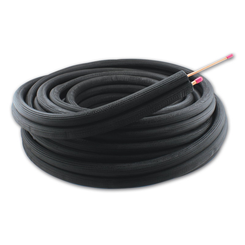
Condensation occurs on a surface when its temperature drops below the dew point of the surrounding air. The dew point is the temperature at which the air becomes saturated with water vapour, and any further cooling will cause that vapour to condense into liquid water. In HVACR systems, pipes carrying chilled water or cold refrigerants for an air conditioner often operate at temperatures significantly below the ambient air temperature, making them prime candidates for condensation if left uninsulated or improperly insulated.
The primary role of insulation in preventing condensation is to ensure that the outer surface temperature of the insulation remains above the dew point of the surrounding air. If the insulation is sufficiently thick and has a low enough thermal conductivity, it will create a thermal barrier that isolates the cold pipe from the warmer, more humid ambient conditions, thus keeping its outer surface warm enough to prevent condensation.
The consequences of uncontrolled condensation can be severe and wide-ranging:
- Water Dripping: Accumulated condensation can drip from pipes, leading to water damage to ceilings, walls, floors, and any equipment located below the pipework.
- Corrosion Under Insulation (CUI): When moisture becomes trapped against the pipe surface beneath the insulation layer, it can create an ideal environment for corrosion. CUI can be particularly insidious as it is hidden from view, potentially leading to significant weakening of pipes and eventual leaks or failures.
- Mould and Mildew Growth: Damp insulation materials and surrounding damp areas provide fertile ground for the growth of mould and mildew. These biological contaminants can degrade indoor air quality and pose health risks to building occupants, particularly those with respiratory conditions or allergies.
- Reduced Insulation Effectiveness: When insulation materials become wet, their thermal resistance properties are significantly diminished. Water is a much better conductor of heat than the still air trapped within dry insulation, so saturated insulation provides little thermal benefit.
Effective condensation control relies on two key factors: ensuring sufficient insulation thickness, as specified by standards like BS 5422 (which provides specific guidance, for example, in Table 7 for chilled water lines and Table 2 for refrigeration pipework under defined ambient conditions), and implementing a continuous, intact vapour barrier for all pipework operating at temperatures below the ambient dew point.
5.2 Minimising Energy Loss: Efficiency Through Insulation
Insulation plays a direct role in minimising energy loss from HVACR pipework, thereby improving overall system efficiency.
- Heat Gain (Cold Systems): For chilled water or refrigerant pipes for an AC unit, which are colder than their surroundings, there is a natural tendency for heat to flow from the warmer ambient environment into the colder pipes. Uninsulated or inadequately insulated pipes will absorb a significant amount of this ambient heat. This unwanted "heat gain" places an additional load on the refrigeration system (e.g., chillers, compressors), forcing it to work harder and consume more energy to maintain the desired low temperatures of the transported fluid.
- Heat Loss (VRF Hot Gas Lines/Heating Systems): Conversely, for pipes carrying hot fluids, such as those in heating systems or the hot gas lines in VRF heat recovery systems, insulation is crucial for preventing heat from being lost to the cooler surroundings before it reaches its intended point of use. This ensures that the heat generated by the system is delivered efficiently, improving the system's effectiveness and reducing wasted energy.
The reduction in energy consumption achieved through proper insulation translates directly into lower operational costs for the building owner or operator, and also contributes to a smaller environmental footprint by reducing greenhouse gas emissions associated with energy generation.
The thermal conductivity of the insulation material (often denoted by the Greek letter lambda, and expressed in W/mK) is a critical property in determining its effectiveness at resisting heat transfer. The lower the thermal conductivity value, the better the material is at insulating. This means that for a given level of thermal resistance, a material with a lower lambda-value can be applied in a thinner layer compared to a material with a higher lambda-value. Materials like phenolic foam are known for their very low thermal conductivities, often allowing for slimmer insulation profiles.
The challenges of condensation control and energy loss prevention are intrinsically linked. A failure in the condensation control strategy, particularly one that leads to wet insulation, will directly and negatively impact the system's energy efficiency. This can create a deteriorating cycle of performance. Wet insulation has a significantly higher thermal conductivity than dry insulation, meaning it conducts heat much more readily. Condensation typically forms when the surface temperature of the pipe or insulation falls below the dew point of the surrounding air, often as a result of insufficient insulation thickness or a compromised vapour barrier. If condensation forms and saturates the insulation material, its thermal resistance plummets. Consequently, the insulation is no longer effectively preventing heat gain (in the case of cold lines) or heat loss (in the case of hot lines). The HVACR system then has to work even harder, consuming more energy, to compensate for this increased heat transfer, thereby exacerbating the very energy loss problem that the insulation was installed to solve.
This situation also significantly increases the risk of CUI and other moisture-related damage. This interrelationship highlights that an initial investment in high-quality, correctly installed insulation, including robust and meticulously sealed vapour barriers for all cold lines, yields benefits not only in preventing water damage and corrosion but also in ensuring sustained energy savings throughout the operational life of the system. Attempting to cut costs by compromising on vapour barrier integrity or the quality and thickness of insulation is invariably a false economy, leading to higher long-term operational and maintenance expenditure. This reinforces the core principles of standards like BS 5422, which address both condensation control and thermal performance.
6. Fire Safety Considerations for Pipe Insulation and Air Conditioner Lag
Fire safety is a non-negotiable aspect of building design and construction in the UK, and the materials used for pipe insulation, including air conditioner lag, are subject to stringent fire performance standards. The choice of insulation can significantly impact how a fire develops and spreads, and how much smoke is produced, all of which are critical factors for life safety and property protection.
6.1 Understanding Euroclass Fire Ratings
The fire performance of construction products, including thermal insulation, is classified in the UK according to the European Standard BS EN 13501-1. This system, known as the Euroclass system, provides a harmonised approach to assessing how materials react to fire and is the legally recognised standard within the UK Building Regulations.
The Euroclass rating is typically presented in three parts:
- Main Classification (Reaction to Fire): This indicates the material's combustibility and its contribution to fire growth. The classes range from A1 (non-combustible, making no contribution to fire) and A2 (limited combustibility) down to F (easily flammable or performance not determined). For pipe insulation, which are linear products, the classification may be denoted with an 'L' subscript, e.g., BL, CL. Mineral wool products, for example, often achieve an A1 or A2L rating.
- Smoke Production: This part of the classification indicates the amount and rate of smoke produced when the material is exposed to fire. It is denoted by 's1', 's2', or 's3'.
- s1: Little or no smoke production.
- s2: Medium smoke production.
- s3: Substantial or high smoke production.
- Flaming Droplets/Particles: This classification indicates whether the material produces flaming droplets or particles when burning, which can contribute to fire spread. It is denoted by 'd0', 'd1', or 'd2'.
- d0: No flaming droplets or particles.
- d1: Some flaming droplets or particles.
- d2: Several or many flaming droplets or particles.
A common high-performance rating for flexible elastomeric foam or foil-faced phenolic foam pipe insulation is, for example, BL-s1,d0 or BL-s2,d0. This indicates a very limited contribution to fire, little or medium smoke production, and no flaming droplets.
6.2 The Transition from UK "Class O"
For many years, "Class O" was the benchmark fire performance requirement for the surface spread of flame and fire propagation characteristics of materials used in many building applications in the UK, including pipe lagging. This classification was defined within the UK Building Regulations and referenced tests from the BS 476 series (specifically Parts 6 and 7).
However, with the drive for harmonisation of standards across Europe and the introduction of CE Marking for construction products, the Euroclass system has now largely superseded the older national classifications like Class O in the UK Building Regulations. While for a period Class O was often considered broadly equivalent to a Euroclass B rating, the Euroclass system provides a more comprehensive and nuanced assessment of a material's overall reaction to fire. Manufacturers of insulation products now test and declare the fire performance of their products against the relevant Euroclass standards. The additional information provided by the 's' (smoke) and 'd' (droplets) classifications within the Euroclass system is particularly important, as these aspects, which significantly impact life safety, were not explicitly quantified by the old Class O rating.
6.3 Requirements in Approved Document B
Approved Document B of the Building Regulations provides specific guidance on the minimum Euroclass fire ratings required for insulation materials. These requirements vary depending on factors such as the type of building (e.g., dwellings versus buildings other than dwellings), the height of the building, and the specific location and application of the insulation material. For instance, in buildings other than dwellings, it is often stipulated that the complete assembly of insulation materials, as placed on the market (whether faced or unfaced), must achieve a Euroclass B-s3, d2 rating or better.
Beyond the reaction to fire of the insulation material itself, Approved Document B also addresses the potential for smoke and toxic fume generation in the event of a fire. Consideration must be given to this, especially when selecting materials for use in enclosed areas or in proximity to air ducts through which smoke or fumes could spread. Furthermore, where pipework and its insulation system penetrate fire-resisting elements of the building structure (such as fire-rated walls or floors), the integrity of that fire separation must not be compromised. The insulation system and any associated fire-stopping measures must maintain the required level of fire resistance of the division through which they pass.
The adoption of Euroclasses means that simply specifying an insulation material as "non-combustible" or "fire-retardant" is no longer sufficient for ensuring compliance or achieving optimal fire safety. A more detailed understanding of the Euroclass scale, from A1 (best) to F (worst), along with the critical subsidiary classifications for 's' (smoke production) and 'd' (flaming droplets), is now necessary. These classifications provide a more complete picture of a material's behaviour in a fire scenario. Approved Document B sets out the minimum performance levels required for different situations. A material might achieve a reasonable main fire classification (e.g., Euroclass C) but still produce a substantial amount of smoke (s3) or generate flaming droplets (d2), both of which pose significant hazards.
Smoke is a primary cause of incapacitation and fatalities in building fires, and flaming droplets can accelerate fire spread to other areas. Therefore, specifiers must look beyond the primary letter classification (A, B, C, etc.) and consider the full designation (e.g., B-s1,d0). A product with a B-s1,d0 rating is considerably safer in a fire than one rated B-s3,d2, even though both might be broadly referred to as "Euroclass B". This distinction is particularly vital in escape routes, high-occupancy buildings, or areas containing sensitive equipment where smoke damage can be as detrimental as direct fire damage. This detailed classification system allows for a more risk-appropriate selection of materials. For example, in a critical facility like a data centre, minimising smoke production (aiming for an s1 rating) would be a key objective to protect valuable equipment and allow for safe shutdown procedures, even if the insulation material used is not strictly A1 non-combustible. This aligns with the overall purpose of Approved Document B, which is to safeguard human life and, where appropriate, protect property from the effects of fire.
7. Conclusion: Investing in Quality Pipe Insulation
The evidence clearly indicates that effective pipe insulation is not merely an ancillary component but a fundamental element of any well-designed and efficiently operating HVACR system within the UK. Its role in conserving energy, preventing damaging condensation, ensuring system longevity, and meeting critical fire safety standards cannot be overstated.
While there is an initial investment associated with the specification and installation of quality pipe insulation, the long-term value derived from this investment is substantial. Significant savings in energy consumption, the prevention of costly damage arising from uncontrolled condensation, corrosion, or freezing, and the extension of the overall lifespan of the HVACR system collectively demonstrate that quality insulation is a sound economic decision.
Adherence to the relevant UK standards, principally BS 5422 for determining insulation thickness and thermal performance, and BS 5970 for guiding correct installation practices, is crucial. Equally important is compliance with the Building Regulations, particularly Part L for energy conservation and Approved Document B for fire safety. Given the technical complexities and the potential consequences of non-compliance or poor workmanship, it is strongly recommended that the design and installation of HVACR pipe insulation, especially in commercial or complex systems, be undertaken by qualified and experienced professionals who possess a thorough understanding of these requirements.
Ultimately, a meticulously insulated HVACR system is a hallmark of quality in both design and construction. It contributes not only to the immediate operational efficiency and safety of a building but also to the broader goals of creating a more sustainable and resilient built environment for the future.
8. UK Legal Disclaimer
The information provided in this article is for general informational purposes only. All information is provided in good faith; however, we make no representation or warranty of any kind, express or implied, regarding the accuracy, adequacy, validity, reliability, availability, or completeness of any information on this site. Under no circumstance shall we have any liability to you for any loss or damage of any kind incurred as a result of the use of this information or reliance on any information provided. Your use of this information and your reliance on any information is solely at your own risk.
This article contains general guidance and does not constitute professional advice. The application and impact of laws can vary widely based on the specific facts involved. Given the changing nature of laws, rules, and regulations, and the inherent hazards of electronic communication, there may be delays, omissions, or inaccuracies in information contained in this article.
Accordingly, the information in this article is provided with the understanding that the authors and publishers are not herein engaged in rendering legal, engineering, technical, or other professional advice and services. As such, it should not be used as a substitute for consultation with professional engineering, technical, or other competent advisers.
Before making any decision or taking any action, you should consult an appropriate professional. We are not responsible for any errors or omissions, or for the results obtained from the use of this information. All information in this site is provided "as is", with no guarantee of completeness, accuracy, timeliness or of the results obtained from the use of this information.
This content should not be used to specify materials or for detailed design purposes. All specifications and designs should be thoroughly checked and verified by qualified professionals against the latest versions of all relevant standards, regulations, and manufacturer data.

Samuel Hitch
Managing Director
Buy Insulation Online.
Leave A Reply
Your feedback is greatly appreciated, please comment on our content below. Your email address will not be published. Required fields are marked *